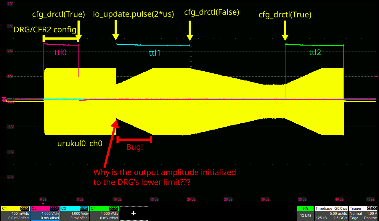
I have isolated this bug extremely well. The self-contained experiment below
- writes an activated amplitude DRG into CFR2,
- sets DRCTL=high,
- waits 5 microseconds,
- then pulses io_update to bring the new CFR2 into effect.
Despite DRCTL=high, the output amplitude is set to the DRG's lower limit at the io_update pulse's rising flank. This is the opposite of what the AD9910 datasheet says on page 30.
Scope traces

Possible explanations
- The rising flank of the io_update pulse somehow resets DRCTL to low just before DRG comes into effect.
- The AD9910 is designed to always initialize the output to the DRG's lower limit as soon as the DRG comes into effect. -> This would be incredibly annoying.
- I am overlooking something and I need smarter people to help me.
The system
The self-contained experiment
from artiq.language.environment import EnvExperiment
from artiq.language.core import kernel, delay, now_mu
from artiq.language.units import ns, us, ms, s, MHz, V
from artiq.language.types import TInt32, TFloat
from artiq.coredevice.i2c import i2c_write_byte
from artiq.coredevice.kasli_i2c import port_mapping
from artiq.coredevice.ad9910 import PHASE_MODE_CONTINUOUS
from artiq.coredevice.ad9910 import _AD9910_REG_RAMP_LIMIT, _AD9910_REG_RAMP_STEP, _AD9910_REG_RAMP_RATE
import numpy as np
# Maps Kasli EEM port indices that are visible on the PCB
# to actual electrical port(?) indices that need to be passed to the FPGA.
KASLI_I2C_BOARD_TO_PORT_MAPPING = [port%8 for port in port_mapping.values()]
# for `artiq.coredevice.i2c.i2c_write_byte(busno, busaddr, data, ack=True)`
# and `artiq.coredevice.i2c.i2c_read_byte(busno, busaddr)`
DIO_SMA_BUS_NUMBER = 0
DIO_SMA_BUS_ADDRESS = 0x7c # = 124 (decimal) or 01111100 (binary)
@kernel(flags={"fast-math"})
def amplitude_to_asf_32(amplitude: TFloat) -> TInt32:
r"""Linearly maps amplitude ∈ [0.0, 1.0] to an unsigned 32-bit integer {0,1,..., 2**32-1}.
Hacking is necessary because the ARTIQ compiler does *not* know unsigned integers."""
if amplitude < 0.0:
raise ValueError("Invalid AD9910 fractional amplitude!")
elif amplitude <= 0.4999999998: # increasing the last digit from 8 to 9 fails
# no clue why minus sign is inverted compared to `rpc_numpy_benchmark`
return np.int32(-round(amplitude * 2 * (1 << 31))) # (1 << 32) produces gargabe
elif amplitude <= 0.9999999998: # increasing the last digit from 8 to 9 fails
# no clue why minus sign is inverted compared to `rpc_numpy_benchmark`
return np.int32(round((1-amplitude) * 2 * (1 << 31))) # (1 << 32) produces gargabe
elif amplitude <= 1.0:
return np.int32(round((1-0.9999999998) * 2 * (1 << 31))) # (1 << 32) produces gargabe
else:
raise ValueError("Invalid AD9910 fractional amplitude!")
return np.int32(0) # prevents compiler crash
class DRGAmplitudeTest(EnvExperiment):
def build(self):
self.setattr_device("core") # artiq.coredevice.core.Core
device_db = self.get_device_db() # dict, DO NOT EDIT!
self.n_kasli_socs = 1 + len(device_db["core"]["arguments"]["satellite_cpu_targets"])
self.setattr_device("i2c_switch0") # artiq.coredevice.i2c.I2CSwitch
self.setattr_device("ttl0") # artiq.coredevice.ttl.TTLInOut
self.setattr_device("ttl1") # artiq.coredevice.ttl.TTLInOut
self.setattr_device("ttl2") # artiq.coredevice.ttl.TTLInOut
self.setattr_device("urukul0_cpld") # artiq.coredevice.urukul.CPLD
self.setattr_device("urukul0_ch0") # artiq.coredevice.ad9910.AD9910
@kernel
def init(self):
r"""
Should be called once after every reboot or power-cycle of the Kasli (SoC).
"""
for i in range(self.n_kasli_socs):
while not self.core.get_rtio_destination_status(i):
pass
self.core.reset()
self.core.break_realtime()
self.i2c_switch0.set(channel = KASLI_I2C_BOARD_TO_PORT_MAPPING[0])
delay(1*us)
i2c_write_byte(
busno = DIO_SMA_BUS_NUMBER,
busaddr = DIO_SMA_BUS_ADDRESS,
data = 0
)
delay(1*us)
self.i2c_switch0.unset()
self.core.break_realtime()
for ttl in [self.ttl0, self.ttl1, self.ttl2]:
ttl.output()
delay(1*us)
ttl.off()
delay(1*us)
self.urukul0_cpld.init()
delay(1*us)
self.urukul0_cpld.cfg_att_en_all(1)
delay(1*us)
self.urukul0_ch0.sw.off()
delay(1*us)
self.urukul0_ch0.init()
delay(1*us)
self.urukul0_ch0.set_phase_mode(PHASE_MODE_CONTINUOUS)
delay(1*us)
self.urukul0_ch0.set_att(0.0)
delay(1*us)
self.core.wait_until_mu(now_mu())
@kernel
def run(self):
# =================================
# ==== HARDWARE INITIALIZATION ====
# =================================
self.init()
self.core.reset()
self.core.break_realtime()
# ===========================
# ==== DDS CONFIGURATION ====
# ===========================
self.urukul0_ch0.set(180*MHz, 0.0, 0.1)
delay(2*us) # Wait for SPI bus write to complete;
# otherwise, scope shows transient effect
# in the first microsecond of the DDS output.
# ==========================
# ==== EXPERIMENT START ====
# ==========================
self.urukul0_ch0.sw.on()
# ============================
# ==== RAMP CONFIGURATION ==== <-- duration marked by ttl0 high state
# ============================
self.ttl0.on()
self.urukul0_ch0.write64(
_AD9910_REG_RAMP_LIMIT,
amplitude_to_asf_32(0.1), # upper
amplitude_to_asf_32(0.05), # lower
)
self.urukul0_ch0.write32(_AD9910_REG_RAMP_RATE, (1 << 16) | (1 << 0))
time_step = 4 / self.urukul0_ch0.sysclk # seconds
self.urukul0_ch0.write64(
_AD9910_REG_RAMP_STEP,
amplitude_to_asf_32(0.05 * time_step / (10*us)), # decrement
amplitude_to_asf_32(0.05 * time_step / (5*us)), # increment
)
self.urukul0_ch0.set_cfr2(drg_enable=1, drg_destination=2)
# AD9910 datasheet page 30 says:
# "if DRCTL = 0, the DRG output is initialized to the lower limit."
# Our first amplitude ramp goes downwards,
# so we do *not* want this initialization.
# To prevent it, we set the DRCTL pin to high
# before activating the ramp.
self.urukul0_ch0.cfg_drctl(True)
self.ttl0.off()
delay(5*us) # After this delay, the state of the DRCTL pin
# should already be high, so the DRG output should
# *not* be initialized to the lower limit
# when the new values of CFR2 come into effect
# with the io_update pulse just below.
# =========================
# ==== RAMP ACTIVATION ==== <-- marked by ttl1 rising flank
# =========================
self.urukul0_ch0.io_update.pulse(2*us) # long pulse to distinuish rising and falling flank
delay(-2*us)
self.ttl1.on()
# =============================
# ==== START DOWNWARD RAMP ==== <-- marked by ttl1 falling flank
# =============================
delay(10*us)
self.ttl1.off()
delay(-1*us) # changing the state of the DRCTL pin via the SPI bus takes approx. 1 microsecond
self.urukul0_ch0.cfg_drctl(False)
# =======================================================
# ==== RAMPING DOWNWARD, THEN STAYING AT LOWER LIMIT ====
# =======================================================
delay(13*us)
# ===========================
# ==== START UPWARD RAMP ==== <-- marked by ttl2 rising flank
# ===========================
self.ttl2.on()
delay(-1*us) # changing the state of the DRCTL pin via the SPI bus takes approx. 1 microsecond
self.urukul0_ch0.cfg_drctl(True)
# =====================================================
# ==== RAMPING UPWARD, THEN STAYING AT UPPER LIMIT ====
# =====================================================
delay(8*us)
# ========================
# ==== EXPERIMENT END ==== <-- marked by ttl2 falling flank
# ========================
self.urukul0_ch0.sw.off()
self.ttl2.off()
delay(10*us)
self.core.wait_until_mu(now_mu())