Hi, I am using artiq 4.0 in trapped ion experiments. I want to use an external clock to synchronize the DDS with other devices.
I only have two clocks, with frequecies 10MHz and 1GHz. Unforutunately, according to the file ad9910.py(C:\Users***\anaconda3\envs\artiq-kasli\Lib\site-packages\artiq\coredevice\ad9910.py), neither clock could be used.
There are two problems.
1.

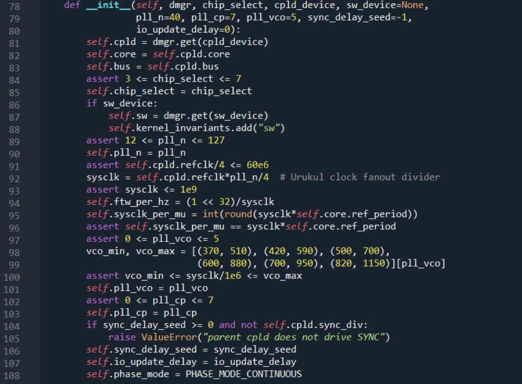
In line 92, we know that sysclk = refclk*pll_n/4. In line 95 and 96, as ref_period = 1e-9 is set in device_db.py file, we know sysclk = 1e9, so if we use refclk = 10MHz, pll_n = 400, and if we use refclk = 1GHz, pll_n = 4.
However, in line 89 "assert 12<= pll_n <= 127", these two cannot work.
When I change the ref_period to 1e-8, in line 98-100, sysclk/1e6 = 100, which is not included in those six situations.
So how I can use these two external clock reference to dds board?
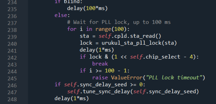
I try to change these values, but it seems these value are decided by hardware. When I change theses value, for example, 12<= pll_n<=1270, the program when wrong with "PLL time out" error(in line 245), which is because the 'sat' value got from urukul board cannot satisfied lock condition.

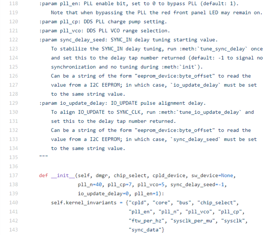
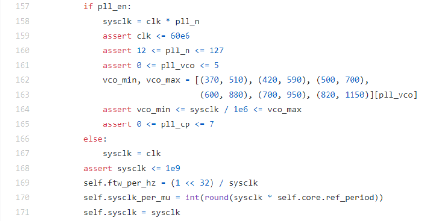
- Our version of Artiq is 4.0, but the ad99100.py file in the repository of github is 6.0 version. There are many different between these two version. In 6.0 version, 'init' function of ad9910.py has an option called "pll_en", which control whether system bypass the pll(phase lock loop) progress.
See next two picture, first is 4.0

, second and third is 6.0


So I want to know what happen if the system bypass the pll progress, how system can use external refernce clock signal as system clock signal?
`class AD9910:
"""
AD9910 DDS channel on Urukul.
This class supports a single DDS channel and exposes the DDS,
the digital step attenuator, and the RF switch.
:param chip_select: Chip select configuration. On Urukul this is an
encoded chip select and not "one-hot": 3 to address multiple chips
(as configured through CFG_MASK_NU), 4-7 for individual channels.
:param cpld_device: Name of the Urukul CPLD this device is on.
:param sw_device: Name of the RF switch device. The RF switch is a
TTLOut channel available as the :attr:`sw` attribute of this instance.
:param pll_n: DDS PLL multiplier. The DDS sample clock is
f_ref/4*pll_n where f_ref is the reference frequency (set in the parent
Urukul CPLD instance).
:param pll_cp: DDS PLL charge pump setting.
:param pll_vco: DDS PLL VCO range selection.
:param sync_delay_seed: SYNC_IN delay tuning starting value.
To stabilize the SYNC_IN delay tuning, run :meth:`tune_sync_delay` once
and set this to the delay tap number returned (default: -1 to signal no
synchronization and no tuning during :meth:`init`).
:param io_update_delay: IO_UPDATE pulse alignment delay.
To align IO_UPDATE to SYNC_CLK, run :meth:`tune_io_update_delay` and
set this to the delay tap number returned.
"""
kernel_invariants = {"chip_select", "cpld", "core", "bus",
"ftw_per_hz", "pll_n", "io_update_delay",
"sysclk_per_mu"}
def __init__(self, dmgr, chip_select, cpld_device, sw_device=None,
pll_n=40, pll_cp=7, pll_vco=5, sync_delay_seed=-1,
io_update_delay=0):
self.cpld = dmgr.get(cpld_device)
self.core = self.cpld.core
self.bus = self.cpld.bus
assert 3 <= chip_select <= 7
self.chip_select = chip_select
if sw_device:
self.sw = dmgr.get(sw_device)
self.kernel_invariants.add("sw")
assert 12 <= pll_n <= 127
self.pll_n = pll_n
assert self.cpld.refclk/4 <= 60e6
sysclk = self.cpld.refclk*pll_n/4 # Urukul clock fanout divider
assert sysclk <= 1e9
self.ftw_per_hz = (1 << 32)/sysclk
self.sysclk_per_mu = int(round(sysclk*self.core.ref_period))
assert self.sysclk_per_mu == sysclk*self.core.ref_period
assert 0 <= pll_vco <= 5
vco_min, vco_max = [(370, 510), (420, 590), (500, 700),
(600, 880), (700, 950), (820, 1150)][pll_vco]
assert vco_min <= sysclk/1e6 <= vco_max
self.pll_vco = pll_vco
assert 0 <= pll_cp <= 7
self.pll_cp = pll_cp
if sync_delay_seed >= 0 and not self.cpld.sync_div:
raise ValueError("parent cpld does not drive SYNC")
self.sync_delay_seed = sync_delay_seed
self.io_update_delay = io_update_delay
self.phase_mode = PHASE_MODE_CONTINUOUS`