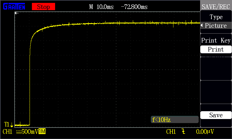
the first wave of the output of the TTL has an obvious rising edge ,but the second or the third wave has not the situation,
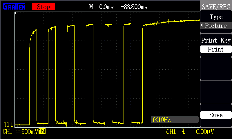
the following are the codes and the picture is output of the ttl4

from artiq.experiment import *
def print_underflow():
print("RTIO underflow occured")

class Tutorial(EnvExperiment):
"""101-两路TTL时序测试V3
"""
def build(self):
self.setattr_device("core")
self.setattr_device("ttl4")

self.setattr_device("ttl5")

self.setattr_device("ttl6")

self.setattr_device("ttl7")

@kernel 
def t4(self):
    delay(77*ms)
    self.ttl4.pulse(5*ms)
    delay(8*ms)
    self.ttl4.pulse(5*ms)
    delay(8*ms)
    self.ttl4.pulse(5*ms)
    delay(8*ms)
    self.ttl4.pulse(5*ms)
    delay(8*ms)
    self.ttl4.pulse(5*ms)
    delay(8*ms)
    self.ttl4.pulse(5*ms)
    delay(8*ms)

@kernel
def run(self):
    self.core.reset()
    delay(20*ms)
    try:
        for i in range(10000000):
            with parallel:
                self.ttl4.pulse(400*ms)
                self.ttl5.pulse(400*ms)
                self.ttl6.pulse(400*ms)
                self.ttl7.pulse(400*ms)
            with parallel:
                self.ttl5.pulse(130*ms)
                self.ttl6.pulse(130*ms)
                self.ttl7.pulse(130*ms)
            with parallel:
                self.ttl6.pulse(400*ms)
            with parallel:
                self.t4()
                self.ttl6.pulse(155*ms)
    except RTIOUnderflow:
        print_underflow()
How is the oscilloscope connected and set up?

    sb10q The oscilloscope starts normallyand then it is connected to the ttl4.of course the 50 ohm setting is not turned on,

    How is it connected to ttl4 (with what probe)?
    Is the behavior present on other channels and with other pulse sequences?

      sb10q i use the DC trigger ,and i change the channel to ttl8,the first wave of the output of the TTL still has an obvious rising edge

      Hi @chaiyu02! I'm helping look into this case. I've also been able to reproduce the rising time phenomenon with my oscilloscope.


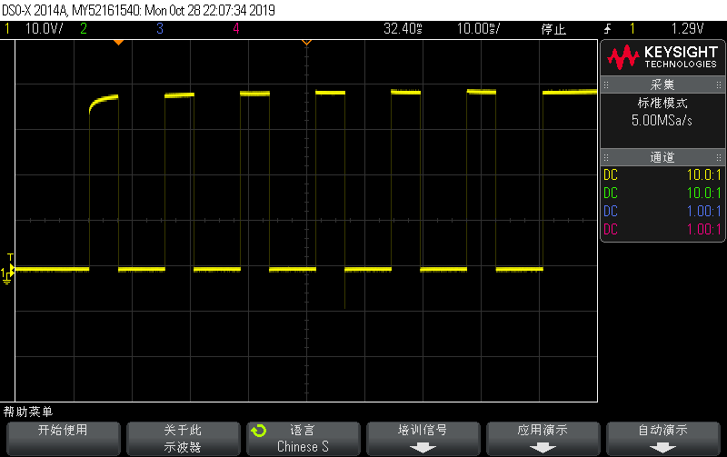
      Fig. 1: TTL4 output, the rising time on the first pulse seems more obvious than the rest; the first 6 pulses also couldn't fully rise to 3.7 V like the final pulse in this period.


      Fig. 2: TTL5 output, which is also similar to TTL7 output.

      From the graph for TTL4, it takes 5 ms (the span of the first pulse) to rise to around 3.4 V. From the graph for TTL5, it also takes around 5 ms to rise to 3.4 V. The rising times for these outputs match.

      However, we do not expect a DIO having this long rising time. We expect the oscilloscope to show clear and straight square-waves at this magnification level.

      The conclusion is the issue comes from the SMA DIO, not your code or ARTIQ.

      Edit: an issue is now open on sinara-hw's repo.

        harry I would like to start by thanking you for your detailed description and replay.what you said is that the interface mode of the DIO,the problem comes from the SMA DIO,but output of the TTL I adopted is BNC DIO.