Consider this scenario: an ARTIQ has a TTL DIO output and an Urukul output. When we try to set the TTL output high and set the frequency or amplitude of the DDS output simultaneously, there is latency between the two commands.
I have experimented with this phenomenon with a script, as shown in the Appendix (see bottom). By running the script and changing the TESTING variable, such latency for setting the frequency and amplitude, respectively, has been captured by an oscilloscope as shown below:
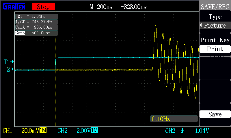
 Fig. 1: Latency between "setting TTL output" and "setting DDS output frequency to 10 MHz".
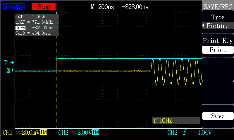
 Fig. 2: Latency between "setting TTL output" and "setting DDS output amplitude to 0.5".
From the graph,
- if the DDS frequency is set while simultaneously setting TTL to high, the latency is 1.34 us.
- If the DDS amplitude is set while simultaneously setting TTL to high, the latency is 1.30 us.
Thus, there is a slightly shorter latency when setting the amplitude compared with the latency when setting the frequency. The latency in either case is also independent of the value of the new frequency or amplitude.
Appendix: Testing script
from artiq.experiment import *
TEST_FREQ = 0x1
TEST_AMPL = 0x2
TESTING = TEST_AMPL # Change this line to switch between testing frequency and amplitude
# Constants
FREQ_MHZ = 10
AMPL = 0.5
class Main(EnvExperiment):
"""
"""
def build(self):
self.setattr_device("core")
self.setattr_device("ttl4")
self.setattr_device("urukul0_ch3")
self.ttl = self.ttl4
self.dds = self.urukul0_ch3
@kernel
def run(self):
self.core.reset()
delay(20*ms)
# TTL
self.ttl.off()
# DDS
self.dds.cpld.init()
self.dds.init()
if TESTING == TEST_FREQ:
self.dds.set(0.)
elif TESTING == TEST_AMPL:
self.dds.set(FREQ_MHZ*MHz, amplitude=0.)
self.dds.sw.on()
delay(20*ms)
with parallel:
# DDS
if TESTING == TEST_FREQ:
self.dds.set(FREQ_MHZ * MHz)
elif TESTING == TEST_AMPL:
self.dds.set(FREQ_MHZ*MHz, amplitude=AMPL)
# TTL
self.ttl.on()
# Delay
delay(1000*ms)
# DDS
if TESTING == TEST_FREQ:
self.dds.set(0.)
elif TESTING == TEST_AMPL:
self.dds.set(FREQ_MHZ*MHz, amplitude=0.)
# TTL
self.ttl.off()