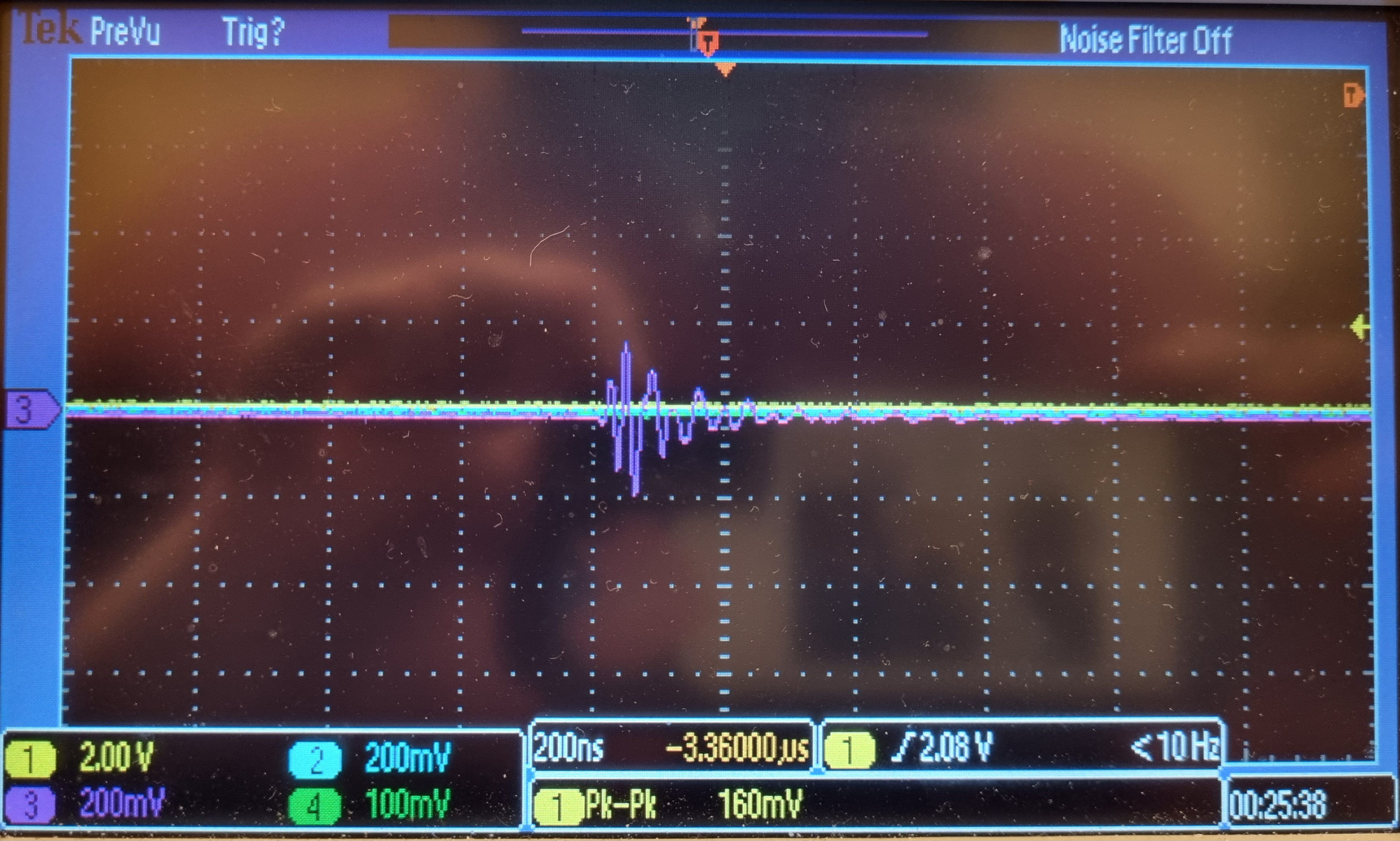
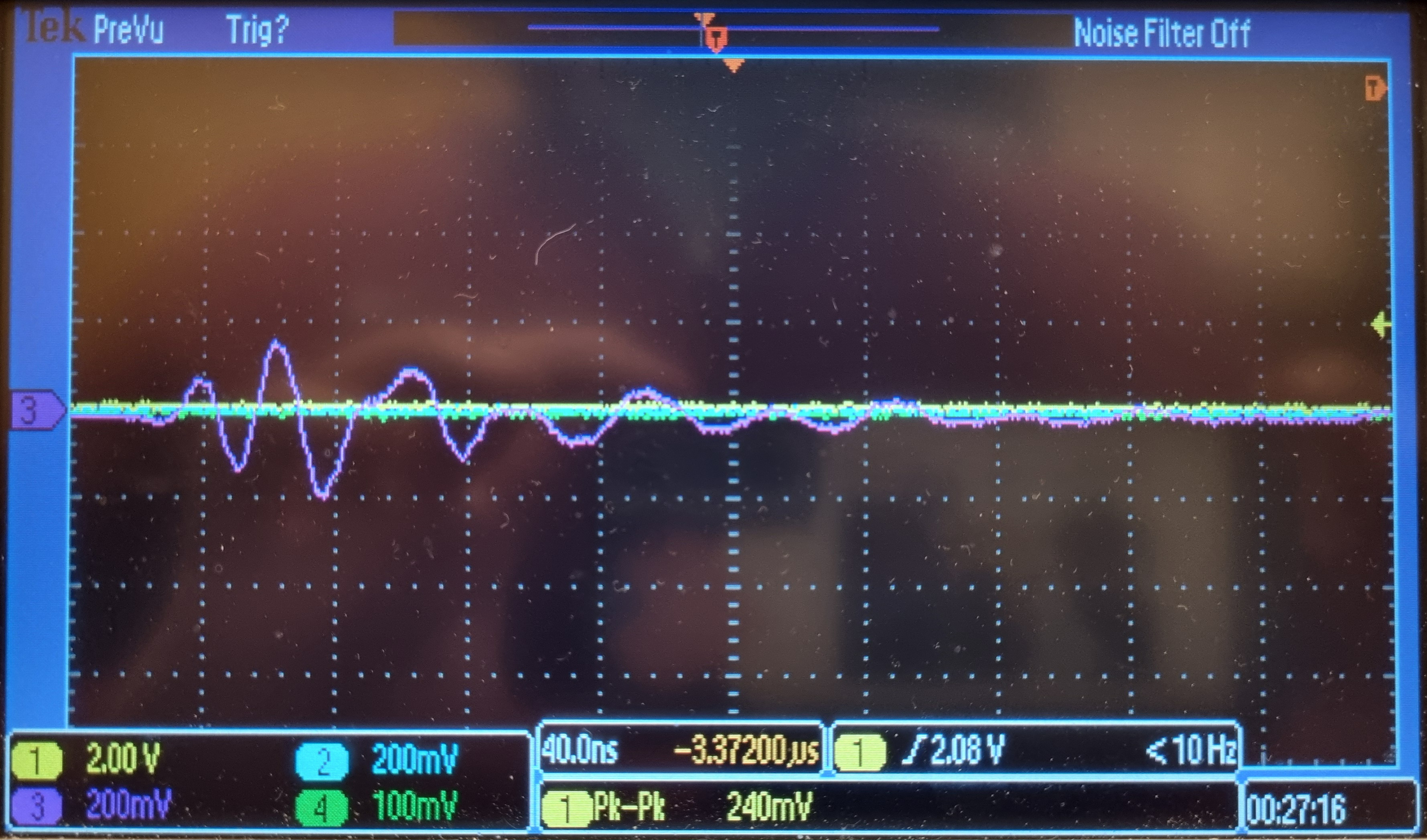
We see the following noise on all output channels of both our 2 Fastino boards, see purple trace (channel 3):
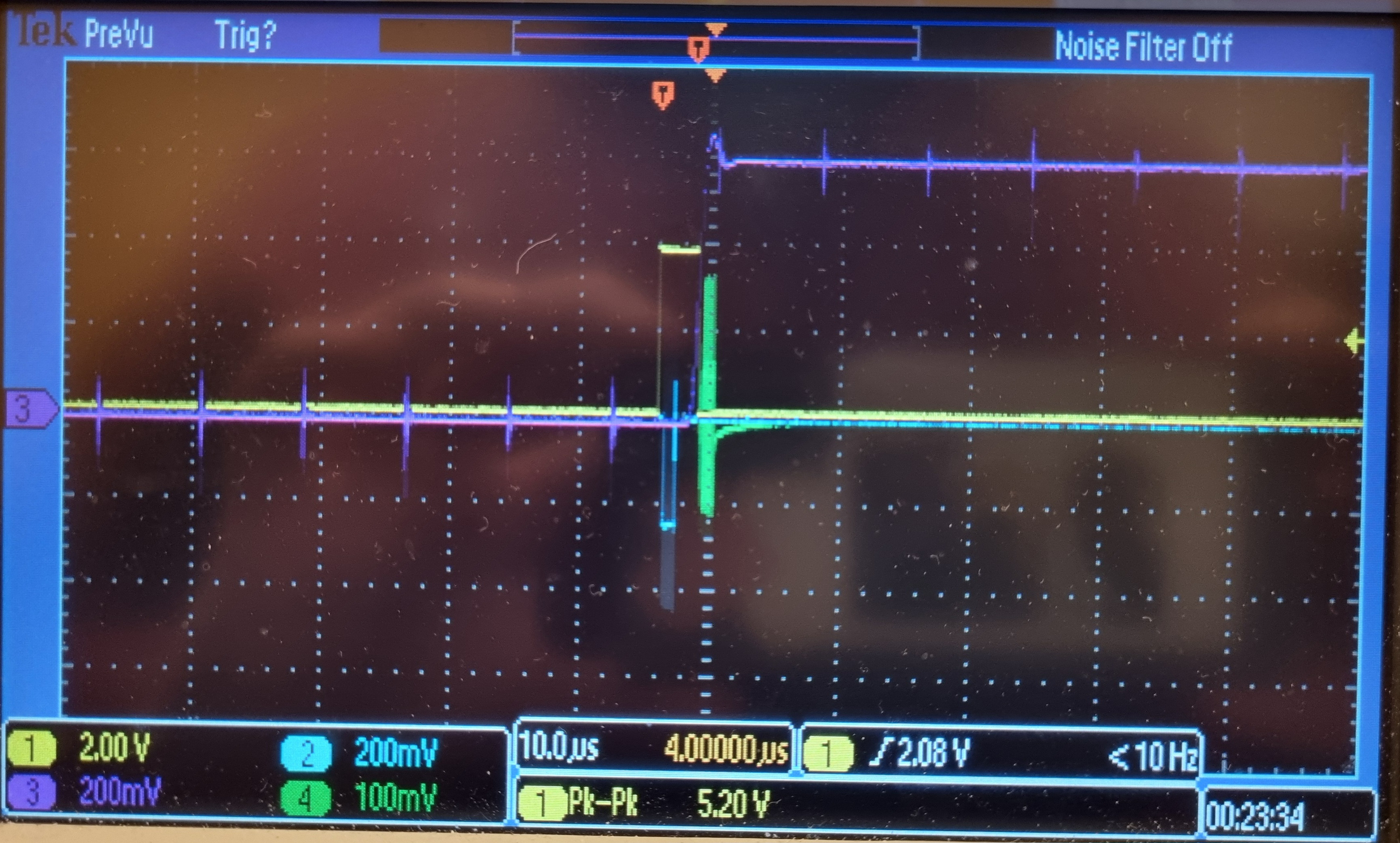
Has anybody else seen such noise on Fastino outputs?
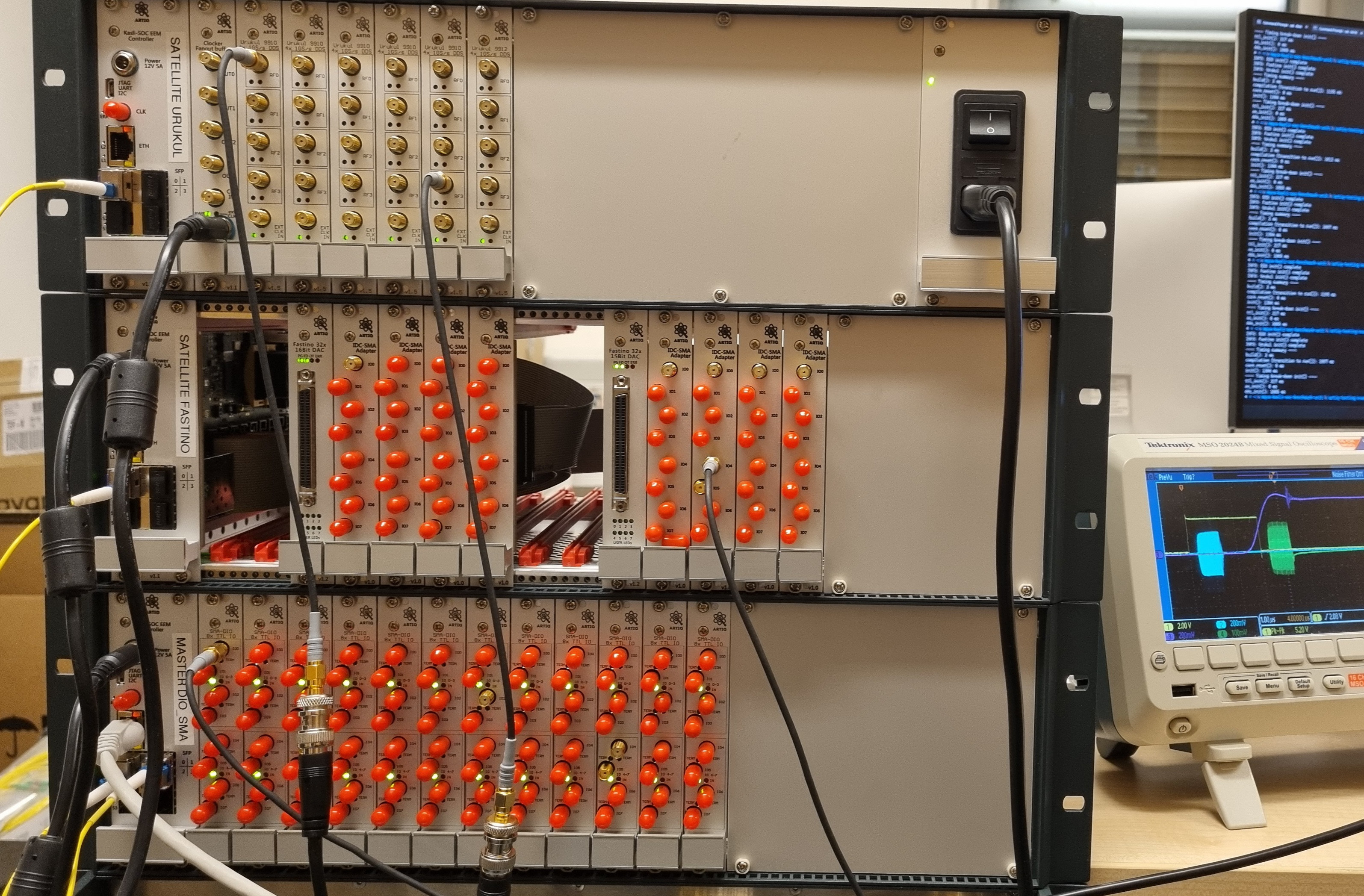
See below for more photos of the noise and for details about our setup.
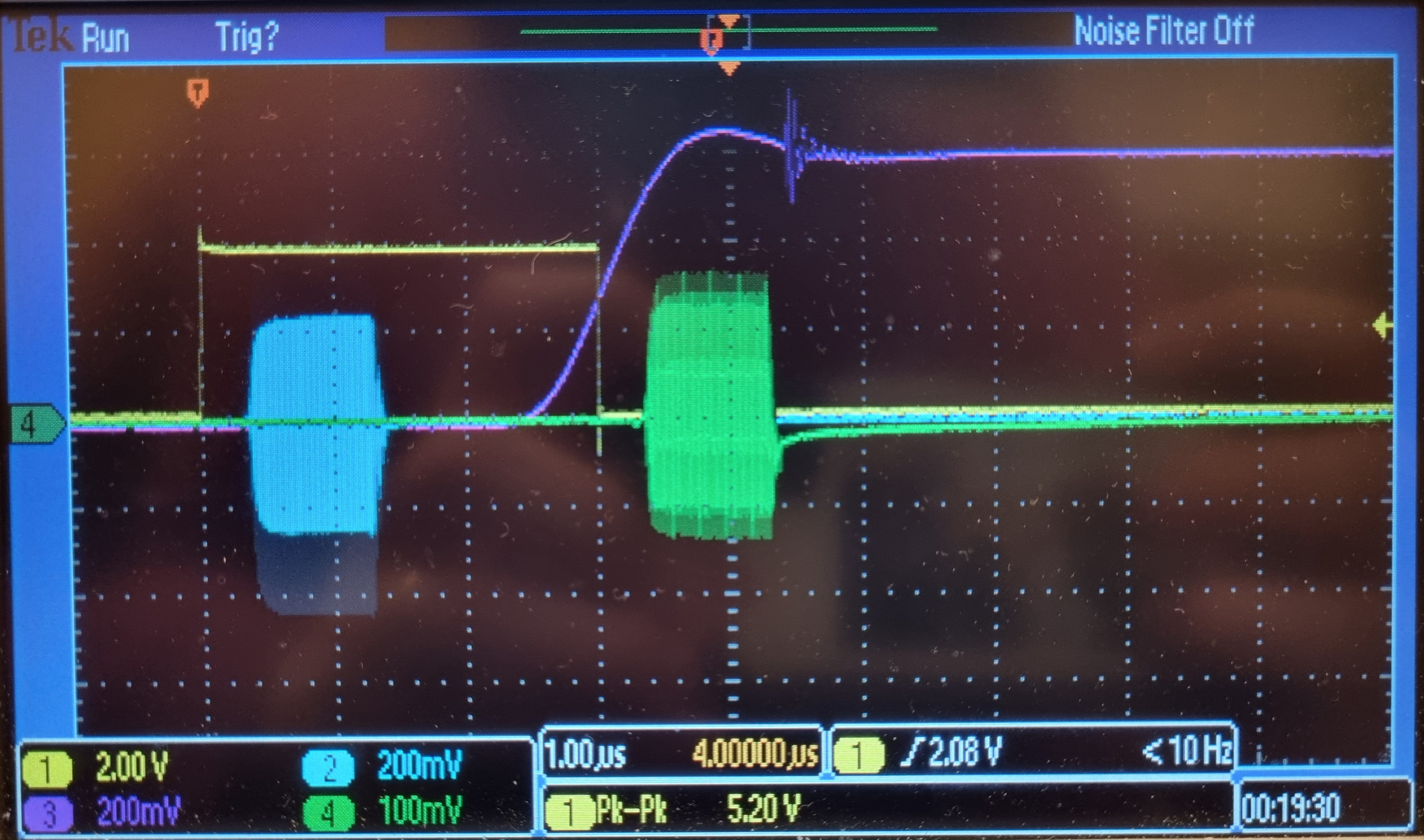
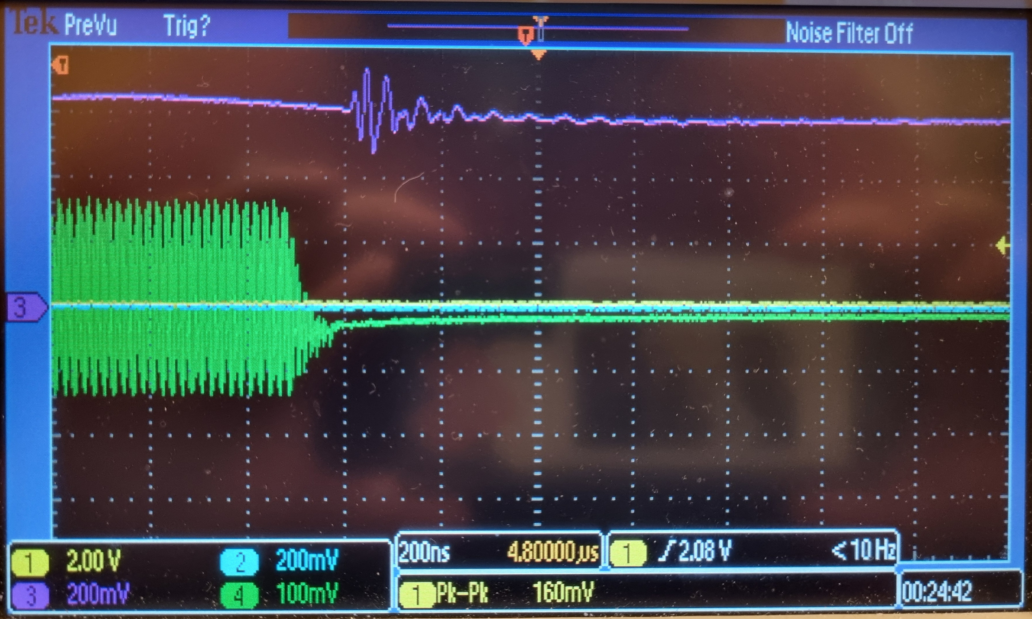
Note: Ignore the weird shape of the green trace (channel 4), the Urukul gets into trouble at f=350 MHz, att=10 dB, ampl=1.0. Similar problems appear at 100 MHz. Nothing strange, I think. The cyan trace (channel 2) looks ok because it's at 250 MHz.
Our setup:
- 1x Kasli SoC v1.1.1 master connected to 12x DIO_SMA v.1.4.1
- 1x Kasli SoC v1.1.1 satellite connected to 2x Fastino v1.2.1
- 1x Kasli SoC v1.1.1 satellite connected to 1x Clocker v1.1rc2 and 6x Urukul v1.5.4
- artiq-zynq commit a0281e498927d5c8467dd18f28aa497cb75150fd: most recent on branch
master right now (January 2025)
- artiq commit 63db4af1fcd9c5cb305a3eee2c0f82bf3de95563: most recent on branch
master right now (January 2025)
More photos of the noise on the Fastino output; it looks the same on all channels of both our Fastino boards:
Code to reproduce:
Requires pip install -e . of tiny custom package artiq-testing!
from artiq.experiment import EnvExperiment, kernel, rpc
from artiq.language.types import TNone, TBool, TInt32, TStr, TList
from artiq.language.units import ns, us, ms, s, MHz
from artiq.coredevice.ad9910 import PHASE_MODE_CONTINUOUS
import artiq_testing as at
class TestSatellites(EnvExperiment):
@rpc
def build(self) -> TNone:
self.t0 = time.time()
self.setattr_device("core") # artiq.coredevice.core.Core
# ---- LED-related channels ----
for i in range(at.NUMBER_OF_LED_CHANNELS):
self.setattr_device(f"led{i}") # artiq.coredevice.ttl.TTLOut
self.led_ch_list = [getattr(self, f"led{i}") for i in range(at.NUMBER_OF_LED_CHANNELS)]
# ---- TTL-related channels ----
self.setattr_device("i2c_switch0") # artiq.coredevice.i2c.I2CSwitch
self.setattr_device("i2c_switch1") # artiq.coredevice.i2c.I2CSwitch
for i in range(at.NUMBER_OF_TTL_CHANNELS):
self.setattr_device(f"ttl{i}")
self.ttl_ch_list = [getattr(self, f"ttl{i}") for i in range(at.NUMBER_OF_TTL_CHANNELS)]
# ---- AO-related channels ----
for i in range(at.NUMBER_OF_FASTINO_BOARDS):
self.setattr_device(f"fastino{i}") # artiq.coredevice.fastino.Fastino
self.ao_ch_list = [getattr(self, f"fastino{i}") for i in range(at.NUMBER_OF_FASTINO_BOARDS)]
# ---- DDS-related channels ----
for i in range(at.NUMBER_OF_URUKUL_BOARDS):
self.setattr_device(f"urukul{i}_cpld") # artiq.coredevice.urukul.CPLD
for j in range(4):
self.setattr_device(f"urukul{i}_ch{j}") # artiq.coredevice.ad9910.AD9910
self.setattr_device(f"ttl_urukul{i}_sw{j}") # artiq.coredevice.ttl.TTLOut
self.urukul_cpld_list = [getattr(self, f"urukul{i}_cpld") for i in range(at.NUMBER_OF_URUKUL_BOARDS)]
self.dds_ch_list = [getattr(self, f"urukul{i}_ch{j}") for i in range(at.NUMBER_OF_URUKUL_BOARDS) for j in range(4)]
self.dds_ttl_list = [getattr(self, f"ttl_urukul{i}_sw{j}") for i in range(at.NUMBER_OF_URUKUL_BOARDS) for j in range(4)]
# ---- load configurations ----
# [b00000000, b00001111, b11110000, ...] for every DIO_SMA board
# [2, 0 , 2, 2, ...] for every TTL channel
(self.dio_sma_board_directions_binary, self.ttl_channel_is_output) = at.get_ttl_directions(
banks_with_inputs = [], # 0-23
verbose = False,
)
self.t1 = time.time()
@kernel
def init(self) -> TNone:
at.set_ttl_directions(
core = self.core,
i2c_switches = [self.i2c_switch0, self.i2c_switch1],
board_directions_binary = self.dio_sma_board_directions_binary,
ttl_ch_list = self.ttl_ch_list,
channel_is_output = self.ttl_channel_is_output,
verbose = False,
)
for ttl_ch in self.ttl_ch_list:
delay(8*ns)
ttl_ch.off()
print("INFO: DIO init() complete")
self.core.break_realtime()
for fastino in self.ao_ch_list:
fastino.init()
for fastino in self.ao_ch_list:
for ch in range(32):
delay(8*ns)
fastino.set_dac(ch, 0.0)
print("INFO: Fastino init() complete")
self.core.break_realtime()
for urukul_cpld in self.urukul_cpld_list:
urukul_cpld.init()
for dds_ch in self.dds_ch_list:
dds_ch.init()
for sw in self.dds_ttl_list:
delay(8*ns)
sw.off()
for dds_ch in self.dds_ch_list:
delay(8*ns)
dds_ch.set_phase_mode(PHASE_MODE_CONTINUOUS)
dds_ch.set_att(10.0)
print("INFO: Urukul init() complete")
self.core.break_realtime()
@kernel
def run(self) -> TNone:
self.core.reset()
self.init()
delay(1*ms)
self.urukul0_ch0.set(
frequency = 250*MHz,
phase = 0.0,
amplitude = 1.0,
phase_mode = PHASE_MODE_CONTINUOUS,
)
self.urukul4_ch3.set(
frequency = 350*MHz,
phase = 0.0,
amplitude = 1.0,
phase_mode = PHASE_MODE_CONTINUOUS,
)
delay(1*us)
self.ttl0.on()
self.ttl_urukul0_sw0.on()
self.fastino0.set_dac(22, 0.6)
self.fastino1.set_dac(28, 0.6)
delay(1*us)
self.ttl_urukul0_sw0.off()
delay(2*us)
self.ttl_urukul4_sw3.on()
self.ttl0.off()
delay(1*us)
self.ttl_urukul4_sw3.off()
If the above link to artiq-testing is broken, just copy from here:
from artiq.coredevice.kasli_i2c import port_mapping
# Maps Kasli EEM port indices that are visible on the PCB
# to actual electrical port(?) indices that need to be passed to the FPGA.
KASLI_I2C_BOARD_TO_PORT_MAPPING = [port%8 for port in port_mapping.values()]
# Maps our own enumeration convention of DIO_SMA boards' banks
# to actual electrical port(?) indices that need to be passed to the FPGA.
# so [7, 5, 4, ...] becomes [7, 7, 5, 5, 4, 4, ...]
KASLI_I2C_DIO_SMA_BANK_TO_PORT_MAPPING = [port%8 for port in KASLI_I2C_BOARD_TO_PORT_MAPPING for i in range(2)]
# for `artiq.coredevice.i2c.i2c_write_byte(busno, busaddr, data, ack=True)`
# and `artiq.coredevice.i2c.i2c_read_byte(busno, busaddr)`
DIO_SMA_BUS_NUMBER = 0
DIO_SMA_BUS_ADDRESS = 0x7c # = 124 (decimal) or 01111100 (binary)
NUMBER_OF_KASLIS = 3
NUMBER_OF_DIO_SMA_BOARDS = 12
NUMBER_OF_FASTINO_BOARDS = 2
NUMBER_OF_URUKUL_BOARDS = 5 # is actually 6 but one board is broken, see https://forum.m-labs.hk/d/877-urukul-v154-ld5-ld6-ld8-and-ld2-remain-dark-ad9910init-crashes
NUMBER_OF_LED_CHANNELS = 2 * NUMBER_OF_KASLIS
NUMBER_OF_TTL_CHANNELS = 8 * NUMBER_OF_DIO_SMA_BOARDS
NUMBER_OF_TTL_BANKS = 2 * NUMBER_OF_DIO_SMA_BOARDS
NUMBER_OF_ANALOG_CHANNELS = 32 * NUMBER_OF_FASTINO_BOARDS
NUMBER_OF_DDS_CHANNELS = 4 * NUMBER_OF_URUKUL_BOARDS
and
from artiq.experiment import rpc
from artiq.language.types import TInt32, TStr
@rpc
def get_type(
obj,
) -> TStr:
return str(type(obj))
@rpc
def to_binary(
number : TInt32,
) -> TStr:
_bin = "{0:b}".format(number)
return "0"*(8-len(_bin)) + _bin
@rpc
def prepend_zeros(
number : TInt32,
total_digits : TInt32,
) -> TStr:
return "0" * (total_digits - len(str(number))) + str(number)
@rpc
def prepend_characters(
string : TStr,
total_digits : TInt32,
character : TStr,
) -> TStr:
return character * (total_digits - len(string)) + string
and
from artiq.experiment import kernel, rpc, host_only
from artiq.language.types import TNone, TBool, TInt32, TList, TTuple
from artiq.language.units import ns, us, ms, s
from artiq.coredevice.i2c import i2c_write_byte, i2c_read_byte
from .console_outputs import get_type, to_binary, prepend_zeros, prepend_characters
from .constants import *
@rpc
def get_ttl_directions(
banks_with_inputs : TList(TInt32), # indices of TTL banks, e.g. [3,6,8]
verbose : TBool = False,
) -> TTuple([TList(TInt32), TList(TInt32)]):
bank_directions = {bank : "output" for bank in range(NUMBER_OF_TTL_BANKS)}
for bank in banks_with_inputs:
bank_directions[bank] = "input"
# convert direction data to 2 useful formats
channel_is_output = [
2*int(bank_directions[bank] == "output") \
for bank in range(NUMBER_OF_TTL_BANKS) \
for ttl_channel_in_bank in range(4)
]
bank_upper = (1 << 4) - 1 # = 0x0f = b00001111
bank_lower = bank_upper << 4 # = 0xf0 = b11110000
board_directions_binary = [
int((bank_upper * (bank_directions[bank] == "input")) | (bank_lower * (bank_directions[bank + 1] == "input"))) \
for bank in range(0, NUMBER_OF_TTL_BANKS, 2)
]
if verbose:
for board in range(NUMBER_OF_DIO_SMA_BOARDS):
print(
"board", prepend_zeros(board, 2), "|",
"i2c_addr", KASLI_I2C_BOARD_TO_PORT_MAPPING[board], "|",
"new_dir", to_binary(board_directions_binary[board]),
"(IO0-4", prepend_characters(
string = bank_directions[2*board],
total_digits = 6,
character = " ",
) + ", IO5-8", prepend_characters(
string = bank_directions[2*board+1],
total_digits = 6,
character = " ",
) + ")"
)
# [b00000000, b00001111, b00000000, ...] for every DIO_SMA board
# [2, 0 , 2, 2, ...] for every TTL channel
return (board_directions_binary, channel_is_output)
@kernel
def set_ttl_directions(
core,
i2c_switches,
board_directions_binary : TList(TInt32),
ttl_ch_list,
channel_is_output : TList(TInt32),
verbose : TBool = False, # print to console
) -> TNone:
for board in range(NUMBER_OF_DIO_SMA_BOARDS):
if board < 8:
sw = i2c_switches[0]
else:
sw = i2c_switches[1]
i2c_addr = KASLI_I2C_BOARD_TO_PORT_MAPPING[board]
sw.set(
channel = i2c_addr,
)
i2c_write_byte(
busno = DIO_SMA_BUS_NUMBER,
busaddr = DIO_SMA_BUS_ADDRESS,
data = board_directions_binary[board],
)
sw.unset()
if verbose:
print(
"board", prepend_zeros(board, 2), "|",
"i2c_addr", i2c_addr, "|",
"new_dir", to_binary(board_directions_binary[board])
)
core.break_realtime()
for channel_id in range(NUMBER_OF_TTL_CHANNELS):
if channel_is_output[channel_id] > 1:
ttl_ch_list[channel_id].output()
else:
ttl_ch_list[channel_id].input()
if channel_id % 10 == 0:
delay(1*us)
@kernel
def set_ttl_bank_to_output(
i2c_switches,
bank : TInt32,
verbose : TBool = False,
channel : TInt32 = -1, # only useful if `verbose == True`
) -> TNone:
# Index of TTL channel 58 in Artiq code: `self.ttl58.channel == 58` (TInt32)
# Physical locations of those TTL channels: Kasli board's EEM{ch % 12} -> DIO_SMA board's IO{ch // 12}
# DIO_SMA board's IO0, IO1, IO2, IO3 (upper 4 channels) are controlled by bank 0 and are all together
# either outputs or inputs. Same for IO4, IO5, IO6, IO7 (lower 4 channels), which are controlled by bank 1.
# We enumerate the banks from 0, 1 (Kasli board's EEM0) to 22, 23 (Kasli board's EEM11).
# Bank index of TTL channel 58: `bank = self.ttl58.channel // 4 == 14` (TInt32)
# `i2c_switch0` controls Kasli board's EEM{0, 1, ..., 7}
# `i2c_switch1` controls Kasli board's EEM{8, 9, 10, 11}
if bank < 16:
sw = i2c_switches[0]
else:
sw = i2c_switches[1]
# We map our bank indices to actual electrical bus(?) indices that need to be passed to the FPGA:
i2c_addr = KASLI_I2C_DIO_SMA_BANK_TO_PORT_MAPPING[bank]
# We "enable one channel", i.e. we select one DIO_SMA board. Source: artiq/coredevice/i2c.py.
# We have confirmed that `self.i2c_switch0` is an instance of `artiq.coredevice.i2c.I2CSwitch`
# via `@proc def type(self, obj) -> TStr: return str(type(obj))`.
sw.set(
channel = i2c_addr,
)
# Read current directions of our DIO_SMA board:
# 1 means TTL_IN, 0 means TTL_OUT
directions = i2c_read_byte(
busno = DIO_SMA_BUS_NUMBER,
busaddr = DIO_SMA_BUS_ADDRESS,
)
# We define an output_mask that is 1 for all channel that belongs to our bank:
# output_mask 00001111 for bank even, i.e. upper 4 channels (IO0, IO1, IO2, IO3)
# output_mask 11110000 for bank odd , i.e. lower 4 channels (IO0, IO1, IO2, IO3)
bank_mask = ((1 << 4) - 1) << (4 * (bank % 2)) # = b1111 << {0 or 4}
# We take `directions` and zero the bits that belong to our bank:
new_directions = directions ^ (directions & bank_mask)
i2c_write_byte(
busno = DIO_SMA_BUS_NUMBER,
busaddr = DIO_SMA_BUS_ADDRESS,
data = new_directions,
)
# We "disable output of the I2C switch", i.e. we de-select all DIO_SMA boards. Source: artiq/coredevice/i2c.py.
sw.unset()
if verbose:
if bank < 16:
sw_nr = "0"
else:
sw_nr = "1"
print(
"channel:", prepend_zeros(channel, 2), "|",
"bank:", prepend_zeros(bank, 2), "|",
"i2c_addr:", i2c_addr, "|",
"sw:", sw_nr, "|",
"dir:", to_binary(directions), "|",
"bank_mask:", to_binary(bank_mask), "|",
"(new_dir) dir ^ (dir & mask):", to_binary(new_directions),
)
@kernel
def print_dio_sma_debug_output(
ttl_ch_list,
i2c_switches,
) -> TNone:
for ch in ttl_ch_list:
# Index of TTL channel 58 in Artiq code: `self.ttl58.channel == 58` (TInt32)
# Physical locations of those TTL channels: Kasli board's EEM{ch % 12} -> DIO_SMA board's IO{ch // 12}
ch_nr = ch.channel
# DIO_SMA board's IO0, IO1, IO2, IO3 (upper 4 channels) are controlled by bank 0 and are all together
# either outputs or inputs. Same for IO4, IO5, IO6, IO7 (lower 4 channels), which are controlled by bank 1.
# We enumerate the banks from 0, 1 (Kasli board's EEM0) to 22, 23 (Kasli board's EEM11).
# Bank index of TTL channel 58: `bank = self.ttl58.channel // 4 == 14` (TInt32)
bank = ch_nr // 4
set_ttl_bank_to_output(
i2c_switches = i2c_switches,
bank = bank,
verbose = True,
channel = ch_nr,
)