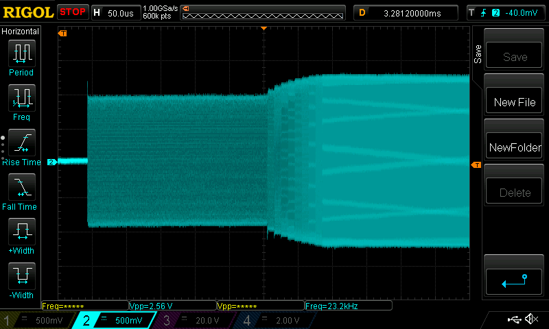
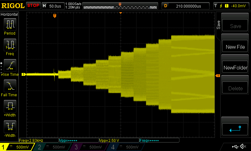
Could some one please advise me on how to correct this issue with regards to the signal cutting out after decreasing the time step for the step address rate to below 1e4? I would really appreciate some guidance.
Sweep frequency DDS
- Edited
I am running into problems with the time step between the samples, in the example code given above the time step is 1e8 which would correspond to 1e8x4ns = 0.4 seconds however going below 1e3x4ns the signal cuts out. I don't understand why this is a problem given that the minimum time to playback ram samples is 4ns and the minimum time for I/O update is in nanoseconds. If I could get this simple ramp up mode working then I should be able to carry onto sinusoidal frequency sweep, could someone please advise me.
I'm just starting to play around with the ram_mode functionality. I'm wondering if you've resolved your issue and how?
Also, is there a way to individually set the DDS profiles on a particular urukul? It seems that self.u.cpld.set_profile(0) sets the profile to 0 for all of the dds chips on the board corresponding to that cpld??
- Edited
jbroz Yes I have created a completed and tested script. You should note there was an issue with the amplitude decreasing with decreasing time step between the RAM samples. This can be fixed from the solution proposed in this github issue. https://github.com/m-labs/artiq/issues/1554. I have attached my tested code below so feel free to test and improve this code.
`
from artiq.experiment import *
from artiq.coredevice import ad9910
import numpy as np
#there are 1024 values for each profile, and the control parameters are the CF, MF, and MD
#The standard value has been set as N = 1024
#first write a simple script and then looking to optimise it.
N = 25
#f1 = 99.*MHz
#f2 = 100.*MHz
#CF, MD, and MF are all in MHz
CF = 100
MF = 0.05
MD = 0.5
#Converting to time period in seconds.
time_period = (1/(MF*MHz))*(1e9)
print(time_period)
time_step= (time_period/N)
print(time_step)
t_step = int(round(time_step/4))
print(t_step, "t_step")
T = int(1e2)
class DDS_freq_ramp(EnvExperiment):
def build(self):
self.setattr_device("core")
self.setattr_device("urukul1_cpld") #2nd Urukul module
self.setattr_device("urukul1_ch3") #Urukul module
self.u = self.urukul1_ch3
def prepare(self):
#create list of frequencies in FTW format to write to RAM
self.f = [0.]*N
self.f_ram = [0]*N
time = np.arange(0,N,1)
amplitude = np.sin(2*np.pi*time/(N-1))
amplitude2 = amplitude*MD
amplitude3 = amplitude2+CF
amplitude4 = amplitude3*MHz
#f_span = f2 - f1
#f_step = f_span / N
#print(f_step)
print(amplitude4)
#I want to see the first step
#print(f1+f_step)
for i in range(N):
self.f[i] = amplitude4[i]
self.u.frequency_to_ram(self.f,self.f_ram)
@kernel
def run(self):
#self.core.reset()
self.core.break_realtime()
'''initialize DDS channel'''
self.u.cpld.init()
self.u.init()
self.u.cpld.io_update.pulse(100*ns)
#self.core.break_realtime()
self.u.set_amplitude(1.)
self.u.set_att(0.*dB)
self.u.set(100.*MHz)
'''prepare RAM profile:'''
self.u.set_cfr1(ram_enable=0) #disable RAM for writing data
self.u.cpld.io_update.pulse(100*ns) #I/O pulse to enact RAM change
self.u.set_profile_ram(start=0, end=N-1, step=t_step, profile=0, mode=ad9910.RAM_MODE_CONT_RAMPUP)
self.u.cpld.set_profile(0)
delay(10 * us)
self.u.cpld.io_update.pulse(100*ns)
'''write data to RAM:'''
delay(10*us)
self.u.write_ram(self.f_ram)
delay(10*us)
'''enable RAM mode (enacted by IO pulse) and fix other parameters:'''
self.u.set_cfr1(internal_profile=0, ram_enable = 1, ram_destination=ad9910.RAM_DEST_FTW, manual_osk_external=0, osk_enable=1, select_auto_osk=0)
self.u.sw.on()
delay(10 *us)
self.u.cpld.io_update.pulse_mu(8)
delay(1 * ms)
self.u.set_cfr1(ram_enable =0)`
han94ros Will do. So far, I've just been playing with the amplitude modulation. But for the most part I'm doing everything the same way as you and it seems to be working fine. I don't know how much there is to improve.
I'm still surprised that you can't set the profiles individually for the different DDS chips on the board (if this is, in fact, the case -- though, I haven't tested it yet).
Also, thanks for pointing out the osk_enable hack! I'm sure that will save me some time tomorrow.
jbroz seems to work if you do not disable the RAM when writing the waveform to another chip/channel. This allows for the setting of independent frequency modulated signals to the different chips.
It says in the manual however that it is strongly recommended that RAM_enable = 0 when performing load/retrieve operations - do you believe writing to the RAM whilst it is still enabled would cause any damage.
Ahh, that makes sense. I think the warning in the manual doesn't apply since the load/retrieve operations are just being performed on a single DDS (even though we've switched the profile setting on all of them). But I could be wrong.
No additional interest or development that I know of.
As always: fund the development and talk to people that can implement it or if you feel up to it, do it yourself.
- Edited
airwoodix
I tried your method and the DDS frequency was stuck in the lower limit for >250 us.

I am not sure how to control/eliminate the time gap (where its stuck at lower limit). Couldn't find anything relevant in the datasheet. Alternatively I have fixed the DRCTL pins to high in the CPLD, and just use the increment fields instead. This is what I got by combining the DRG (frequency) and RAM (amplitude).

Amplitude and frequency changes simultaneously at a defined interval.
Are there any interest for this CPLD patch?
Nvm, just enable load LRR @ I/O Update in CFR1. See the DRG usage in ARTIQ.